Load Balancing MSMQ messages

I am currently writing a database-driven .Net application which needs to send MSMQ messages load balanced across a variable number of machines.

The case scenario is the following:

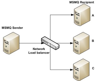
A server needs to send MSMQ messages to servers A, B and C (we choose 3 MSMQ message recipients for the purpose of this example). The original idea was to put a network load balancer (NLB) between the machine sending MSMQ messages and the recipients.

MSMQ Messages Load Balancing with Network Load Balancer (NLB)
If the “MSMQ Sender” machine pictured above sends 75 MSMQ messages, the goal is for machines A, B and C to receive 25 messages each. As we know that a network load balancer distributes load on a connection basis, we were hoping that messages would be load-balanced if the .Net code was creating a new System.Messaging.MessageQueue object for each MSMQ messages sent to the NLB. To be more precise, we were hoping that a new connection to the NLB would be created each time we send a MSMQ message with a new instance of the MessageQueue object.

This was pure speculation and a quick test proved that it did not hold; using a simple network load balancer, all the messages were pushed to a single destination server. This happens because connections are re-used within the MSMQ Windows Service, regardless of how the .Net code is written (as a reminder, the .Net class MessageQueue is just a wrapper around the MSMQ Windows service).

Because traffic is load-balanced on a connection basis (not on a message basis) and because the same TCP connection is re-used by the MSMQ service, the NLB forwards all the traffic to the same destination machine. Would the server send 100 MSMQ messages to the NLB, 100 messages would be forwarded to the same target machine as they are all sent using the same underlying TCP connection.

As we have very little control over the way connections are managed within the MSMQ Windows Service, we had to part away with this simple NLB solution and implement an ad-hoc solution.
We chose to implement the load balancing feature in the .Net application itself. The only addition needed to the existing software is a way to configure it so that it can send MSMQ messages to different queue paths. A simple isolated class, module or piece of code could easily do that.

Server Load Balancing: Algorithms

Before choosing how to implement the solution, let’s have a look at different ways (algorithms) on how to implement load balancing.

  • Random Allocation
    In a random allocation, the traffic (MSMQ messages in our case) is assigned to any server picked randomly among the group of destination servers. In such a case, one of the server may be assigned many more requests to process while the other servers are sitting idle. However, on average, each server gets an approximately equal share of the load due to the random selection.
    Pros: Simple to implement.
    Cons: Can lead to overloading of one server or more while under-utilization of others.
  • Round-Robin Allocation
    In a round-robin algorithm, the traffic is sent to the destination server on a rotating basis. The first request is allocated to a server picked randomly from the group of destination server. For subsequent requests, the algorithm follows the circular order destination servers are listed. Once a server is assigned a request, the server is moved to the end of the list and the next server is chosen for the following request. This keeps all the servers equally assigned.
    Pros: Better than random allocation because the requests are equally divided among the available servers in an orderly fashion.
    Cons: The round robin algorithm is not good enough for load balancing if technical specification of the servers part of the destination group differs greatly (making that the load each server can handle differs greatly).
  • Weighted Round-Robin Allocation
    Weighted Round-Robin is an advanced version of the Round-Robin that takes in account server capability. In case of a weighted round-robin, one can assign a weight to each server in the destination group. For example, if the server group consists of 2 servers and that one server is capable of handling twice as much load as the other, the powerful server gets twice the weight factor. In such a case, the application would assign two requests to the powerful server for each request assigned to the weaker one. In effect, a server with more weight will receive load proportionally to their weight factor.
    Pros: Takes care of the capacity of the servers in the group.
    Cons: Does not consider advanced load balancing requirements such as processing time for each individual request.

We have chosen the Weighted Round Robin algorithm as it is the most advantageous load balancing algorithm to implement easily.
We have chosen to implement the algorithm in T-SQL, but it could be easily implemented in a singleton class in any language such as C# or Java. I will explain why and how in a next blog post: T-SQL Weighted Round Robin Algorithm.

SQL Server Execution Plan Tutorial

Here is a great article written by Grant Fritchey on the basics of analyzing execution plans on SQL Server. It is actually the first chapter of his book on the topic. Yes, a whole book on SQL Server Execution Plans! I haven’t read the whole book but it should probably reveal itself very interesting for DBAs.

Most of us are familiar with the graphical representation of execution plans but Grant Fritchey shows us how to also get execution plans in an XML format and how they actually give more information that their graphical counterpart.

XML executions plans can be saved into files (.sqlplan) and can be viewed either in their XML form or in a graphical form. Being able to save execution plans in a file is very convenient as it makes it easy to share it with DBAs and peers to ask them about their opinion on a slow running query.

Note that on my machine I actually had to edit the .sqlplan file as the first line of the file was a piece of text reading “Microsoft SQL Server 2005 XML Showplan”. This made that the XML file was not well-formed and so could not be loaded by SQL Server Management Studio – this might be fixed in a later Service Pack or hotfix. Once I removed the line of text, I could successfully open the .sqlplan file in SQL Server Management Studio and see the graphical representation of the execution plan. I could also open the file in a text or XML editor and thus see the execution plan in a textual manner. I think that both approaches can prove themselves being complimentary.

The article also shows us how to collect XML execution plans through SQL Server 2005’s Profiler tool. Once execution plans are collected from the server they can be analyzed by DBAs and developers. This can reveal very useful when you want to profile and analyze activities on production environment where you can’t play with data as freely as on a development environment.

For my own sake, I have summarized the introductory materials on the topic hereunder. You might choose to not read it as it is anyway based on the article written by Grant Fritchey.

Execution Plan Introduction.

When you are tuning T-SQL code for performance on SQL Server, the most important information available to you is the Execution Plan. It tells you what kind of JOIN operations and other algorithms are executed as well as what indexes are used. This kind of information will reveal being crucial on poorly performing queries that you need to optimize.

Please keep in mind that this discussion is focused on DML T-SQL.

DML stands for Data Manipulation Language and is aimed at fetching or manipulating data. Basically, it is any SELECT, INSERT, UPDATE and DELETE statement.

DDL stands for Data Definition Language and is aimed at defining data structures. Basically, it is any CREATE, DROP and ALTER statement. DDL statements do not need any query optimization because there is always only 1 way to execute those statements. For example, there is only 1 way to create a table or an index.

When executing a T-SQL query, the T-SQL code is interpreted into instructions understandable by the Database engine. The Database engine is made of multiple processes/sub-engines but 2 are of particular interests regarding Execution Plans: the Relational Engine and the Storage Engine.

Note that in the context of this text, a Process does NOT mean a Windows Process but rather has the more generic meaning of a collection of instructions processing some data. It can be seen as a software module or component.

The Relational Engine.

The Relational Engine is responsible for 3 processes which are of interest in our study:

  • The Parser. The Parser receives the T-SQL query as input and outputs a parse tree or query tree. The parse tree represents the logical steps necessary to execute the query.
  • The Algebrizer. The Algebrizer receives the parse tree from the Parser process as input and resolves all datatypes, names, aliases and synonyms. The output is binary information called the query processor tree.
  • The Query Optimizer. The query optimizer is a piece of software that models the way in which the database relational engine works. Using the query processor tree together with the statistics it has about the data and applying the model, the Query Optimizer works out heuristically what it thinks will be the optimal way to execute the query – that is, it generates an optimized estimated execution plan.

The Storage Engine.

The Storage Engine will execute the estimated execution plan except if it judges that it should be modified. It could be the case if:

  • The estimated execution plan exceeds the threshold for parallel execution.
  • The statistics used to generate the plan are out of date.
  • The estimated execution plan is invalid (for example it creates temp table and so contains DDL statement)

The final execution plan, called the actual execution plan is what is actually executed by the Storage Engine. It might or might not be the same as the estimated execution plan.
Note that generally, there won’t be any differences between the esti¬mated and actual execution plans.

Execution Plan Cache.

As it is expensive for the Server to generate execution plans, SQL Server will keep and reuse plans wherever possible. As they are created, plans are stored in a section of memory called the Plan Cache.

Once the estimated execution plan is created, and before it gets passed to the storage engine, the optimizer compares this estimated plan to actual execution plans that already exist in the Plan Cache. This reuse avoids the overhead of creating actual execution plans. This is obviously beneficial for large and complex queries but also for simple queries which could potentially be called very often (hundreds or thousands of time).

Execution Plans can be removed from the cache in the following scenarios:

  • Memory is required by the system.
  • The “age” of the plan (its time-to-live) has reached zero.
  • The plan isn’t currently being referenced by an existing connection.

Also, cached execution plans might not be reused if an execution plan needs to be recompiled. Certain events and actions can cause a plan to be recompiled. Grant Fritchey enumerates those events in his article.

New Features in Visual Studio 2008

In this post I will go through some Visual Studio 2008 tools and features I found interesting.

1. Unit Test Tool

In VS 2008, Unit Testing is facilitated through a unit test class code generator.

Unit Testing is the act of having a piece of code which only purpose is to test another piece of code, this code being part of the end product. It is a particularly tedious task, so having a unit test code generator is very handy.

A Unit Test class is used to test a class that is part of the software being built. If every classes of a software has a matching class used to unit test it, all the code will be unit tested. Unit testing is the lowest level of Quality Assurance, it does not test the software as a whole neither on its external functionalities but rather makes sure that any testable piece of code part of the software is behaving as it should.

You should consider doing Unit Testing as:

  • It creates test units to check if the code is producing expected results.
  • It improves code coverage. Code coverage is a number telling how many percent of the code has actually been tested. The higher value the more confident we can be in the quality of the code (as it means that a large part of the code returns expected values).

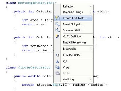
To generate a Unit Test class in VS 20008, simply right-click on any class definition and select the Create Unit Tests option to call the unit test generator tool.

Visual Studio 2008 - Create Unit Test Class
This will create a Unit Test class in a separated project dedicated for Unit Testing, this way your Unit Test code and the actual code are separated in different projects and so code is neatly kept separated.

Note that if you try to generate a Unit Test Class for a class that has private or internal modifiers, VS2008 will add a special InternalsVisibleTo attribute in your original project so that your Unit Test project (and only that one) has access to all private, internal and protected methods and classes of the original project containing the classes you want to unit test. This means that the attribute is not added at the class level but at the project level in the AssemblyInfo.cs file.

Moreover, as it can be seen hereunder, only the Unit Test project (here called CalculatorTest) will have access to internal classes and methods:

[assembly: System.Runtime.CompilerServices.InternalsVisibleTo(“CalculatorTest”)]

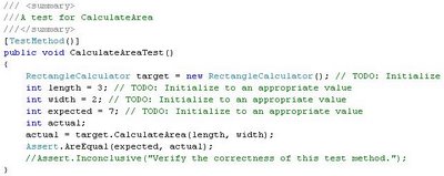
Once the Unit Test classes are generated, you will have to go into them, inspect the code and set input values that will be used to call the methods that need to be tested and also set the expected result value that should be returned by the method. This way, the actual value returned can be compared with the expected value to decide if the test was conclusive or not. There are TODO sections declared in the generated code so that you can easily locate where to set test values.

In the example hereunder, values are set for the length and width of the rectangle and the variable expected contains the pre-calculated area of the rectangle so that we can check if the output of the method is equal to what should be returned. If the value returned by the method is not what is expected, that means that the unit test fail and that there is a bug in the tested method. Visual Studio will clearly show in the test results what unit test succeeded or failed.

Lastly, do not forget to comment out the Assert.Inconclusive() method call.

Visual Studio 2008 - Initialize parameter values for Unit Test
The Test project creates a vsmdi file in the solution item folder, named after the solution name, Calculator.vsdmi for a Visual Studio solution called Calculator.

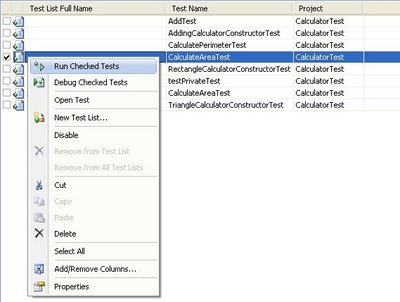
To actually test some or all the unit test methods, open the vsdmi file, select the methods that you want to test, right-click on the list of methods and select Run Checked Tests.

Visual Studio 2008 - Choose Method To Unit Test
Once the test ran, the result will be displayed showing if the test succeeded, failed or was inconclusive.

Visual Studio 2008 - Unit Test Result Window

2. Object Test Bench

If you do not have the time to create full blown Unit Test but still want to test some of your classes and/or methods, there is a quick and dirty way to do it by using the Object Test Bench tool. The tool can call static methods on classes and create object instances of classes so that instance methods can be called ad-hoc. Methods can thus be tested very simply, in a similar way as when you chose to execute a Stored Procedure in SQL Server Management Studio and that a window pops up to let you input the SP parameters.

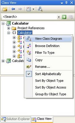
To use the Object Test Bench, you need first to create Class Diagram of your project. To do so, click on the Class View of your Visual Studio project, select the root namespace of your project, right-click on it and choose the View Class Diagram option.

Visual Studio 2008 - Generate Class Diagram From Source Code
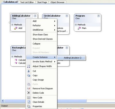
Once the class diagram is created you can call the Object Test Bench tool by either calling a static method on the class or one of the class constructor so that you will be able to call an instance methods after the object is instanciated.

In my case I want to test the Add() method to check if my Calculator object correctly adds numbers. To do so I first instanciate a Calculator object which opens the Object Test Bench window under the class diagram. After the object is created in memory and appears in the Object Test Bench window, I can chose to call any method of the object. I will thus dynamically call the Add() method through the Visual Studio IDE and check if the method returns a correct result.

Visual Studio 2008 - Start Object Test Bench Tool - Create Object Instance
Visual Studio 2008 - Start Object Test Bench Window
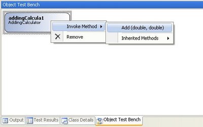
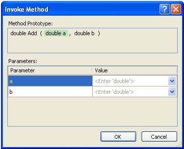
A window will pop up so that you can give values to the input parameters.

Visual Studio 2008 - Object Test Bench Invoke Method And Set Input Parameters
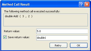
Once the parameters are entered and you click on OK, a pop up window will display the result. You can choose to save the result in a variable so that you can re-use it later. For example you could re-use the variable as a parameter to call another method that you want to test-bench. This way, in a few clicks, you can create a bunch of objects and then re-use them later to call methods that take complex-type objects as parameter.

Visual Studio 2008 - Object Test Bench Invoke Method Result Window

3. Generate Method Stub (only for C#)

It is a code generation feature that creates methods before they exist; the method created is based on the call to that method. Once the call to the method is made, Visual Studio 2008 IntelliSense will give you the option to generate a method stub matching the call to that method, with the matching input parameters and return type.

Visual Studio 2008 - Generate Method Stub
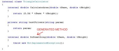
The generated method will be created in the matching class and its stub implementation will simply throw a NotImplementedException.
Visual Studio 2008 - Generate Method Stub Result
Note that this code generation feature is only available for C#.

4. Refactoring Tools (C# only)

Refactoring is making changes to a body of code in order to improve its internal structure without changing its external behavior.

– Martin Fowler

It is useful concept to make code cleaner and more understandable/readable.

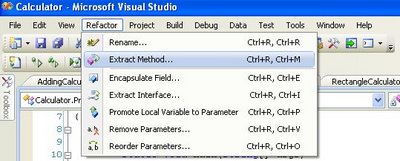
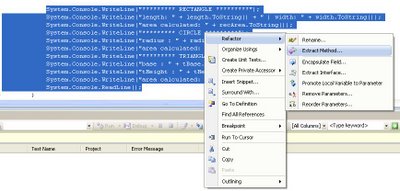
A typical refactoring case is to break up a lengthy method into separate methods. To do so, you can highlight a piece of a code, right-click on it (or go to the Refactor menu of Visual Studio) and choose Extract Method. This will generate a method containing the highlighted code as well as calling the generated method from the original location.

Refactor menu in Visual Studio 2008:

Visual Studio 2008 - Refactor Menu
Refactoring code by creating a method to shorten the original code, it is the action of extracting a method from a piece of code.

Visual Studio 2008 - Refactoring A Method
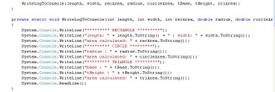
The example here above will create a method containing the highlighted code and replace the original code by a call to the generated method (which I called WriteLogToConsole):
Visual Studio 2008 - Refactoring, Generated Method

5. The .Net Framework Source Code

It is possible to go through the source code of the .Net Framework while debugging. Here are the steps I did to make it work:

1. Install the hotfix KB 944899 – Visual Studio 2008 performance decreases when you step through source code that you downloaded from Reference Source Server.

2.Configure Visual Studio debugger to be able to step in the .Net Framework Source Code:

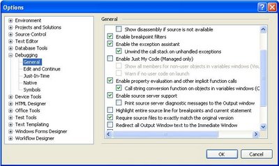
  • Uncheck Enable Just My Code (Managed only).
  • Check Enable source server support.

Visual Studio 2008 - Configuring Visual Studio For Framework Source Code Debugging
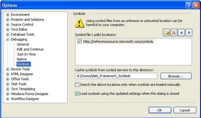
3.Configure the Symbols part of the Visual Studio debugger options so that Visual Studio know where to download the .Net Framework debugging symbol (.pdb files) and source code.

  • Set the Symbol file (.pdb) location to be: http://referencesource.microsoft.com/symbols
  • Set a Cache location folder where the .Net Framework pdb and source code files will be stored. Make sure it is a location that your account has read/write access to. For example, a folder under your user hive.
  • Clear the Search the above locations only when symbols are loaded manually if you want that Visual Studio automatically download symbols and source code while you step in .Net Framework code (F11 shortcut key). Note that if your project is big and references many libraries, downloading all the debugging symbols will be slow at the first debug. If you prefer to load symbols only when needed, keep that box checked. You will then have to download debugging symbols and source code on demand by right-clicking the appropriate dll in the stacktrace and choose Load Symbol.

Here is how I configured my Visual Studio:

Visual Studio 2008 - Configuring Visual Studio Framework Source Code Symbol Location
Visual Studio 2008 is now all set to debug and step in .Net Framework Source Code!

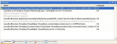
While debugging, we can now see that the debugger call stack contains detailed file and line number information for the .NET Framework classes and methods:

Visual Studio 2008 - Debugger Call Stack
Example of use:

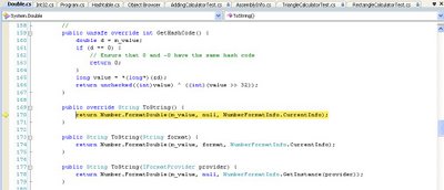
In the following screenshot, I stepped in a line of code that calls the ToString() method on a Double type, this makes that the mscorlib pdb file is downloaded as well as the source code for the Double structure so that I can actually debug into the Double type and see its implementation as written by the .Net team. That is something I find really cool and I think has been missing for a long time!

Visual Studio 2008 - Step In .Net Framework Source Code

Modules Window:

While you are debugging, you can bring up the Modules Wwndow by hitting the ALT+CTRL+U keys. This window shows all the dll loaded by the debugger and let you see which dll has debug information loaded and which does not. You can manually load debugging symbols from that window by right clicking on the library you want to load the symbols for and select the Load Symbols option.

Visual Studio 2008 - Debugger Modules Window

List of assemblies currently available at the time of writing for symbol/source loading:

  • Mscorlib.dll
  • System.dll
  • System.Data.dll
  • System.Drawing.dll
  • System.Web.dll
  • System.Web.Extensions.dll
  • System.Windows.Forms.dll
  • System.XML.dll
  • WPF (UIAutomation*.dll, System.Windows.dll, System.Printing.dll, System.Speech.dll, WindowsBase.dll, WindowsFormsIntegration.dll, Presentation*.dll, some others)
  • Microsoft.VisualBasic.dll

For reference, here is a lengthier blog post by Shawn Burke with more information regarding .Net Framework Source Code debugging.

6. SQL Metal

SQL Metal is used to help implementing LINQ to SQL scenarios. It is a command-line utility (sqlmetal.exe).

SQL Metal can:

  • Generate source code and mapping attributes or a mapping file from a database.
  • Generate an intermediate database markup language file (.dbml) for customization from a database.
  • Generate code and mapping attributes or a mapping file from a .dbml file.

What is a mapping file?
A mapping file is an XML file to specify mapping between the data model of the database and the object model of the .Net code. It keeps the mapping code out of the application code which helps in keeping the code cleaner and leaner. Moreover, since it is XML (like any other .config file) it can be changed without having to rebuild the application code.

Check out MSDN documentation for more information about SQLMetal.

7. Visual Studio 2008 Product Comparison

Great comparison between the different functionalities available on each edition of Visual Studio 2008: http://www.microsoft.com/en-us/download/details.aspx?id=7940

Promoted property vs distinguished field – tutorial

First of all while many people talk about Promoted Property, the official term is Promoted Field, as defined in the MSDN documentation and also visible in Visual Studio’s BizTalk Schema Editor. I will nevertheless keep using the term most people are familiar with but I will consider both terms as synonyms.

Part 1 & 2 is a tutorial on how to create promoted properties and distinguished fields through the Schema Editor and the BizTalk’s API while part 3 is discussing about performance and differences between Promoted Properties and Distinguished Fields. You might only be interested in the 3rd part of this article if you already are a seasoned BizTalk developer.

1. Promoted Properties (Promoted Fields)

1.1 What are Promoted Properties?

Promoted Properties are Message Context Properties that are flagged as promoted; being promoted it allows the Message Engine to route messages based on their value, and being in the message context allows doing so without having to look at the message payload (which would be an expensive operation). Promoted Properties are the most common way to enable content-based routing. They are available to the pipelines, adapters, Message Bus and orchestrations.

Promoted Fields (= Promoted Properties) are PROMOTED in the message context by the receive pipeline when a message is received on a port. It is usually the job of the disassembler pipeline component such as the XML and Flat File disassembler but any custom pipeline component can also do it.

1.2 How to promote properties?

As stated in a previous post I wrote, BizTalk Messaging Architecture, message context properties are defined within a property schema and so all promoted properties must be defined in a custom property schema.

The action of promoting a message element to a promoted property creates a message context property that will contain the message element value and flags it as promoted so that it is available for routing.

There are 2 ways to promote a message element:

1. Quick promotion

Quick promotion is the simplest way to create a promoted property. Simply right click on the element’s node and choose Quick Promotion (see Fig 1.1). When choosing this option, Visual Studio will create a property schema called PropertySchema.xsd and add in the message’s schema a reference to the generated property schema.

Each property promoted this way will create a corresponding element in the property schema with the same name and type as defined in the message’s schema.

This means that when using quick promotion, the promoted property element name will always be the same as the message’s element name. If you have several elements with the same name, you might want to use manual promotion instead to avoid confusion or avoid having a property value overridden.
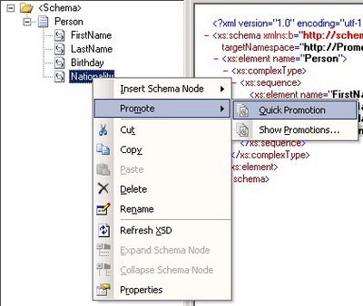
Biztalk promoted properties - quick promotionFig. 1.1 Quick Promotion

2. Manual Promotion

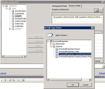
To manually promote a property, a property schema must be created with the elements that will hold the promoted property values. To create a property schema, you need to add a new item in your BizTalk solution, and chose Property Schema as the type of file (see Fig. 1.2). Once all the elements are created in the property schema, you associate the property schema with the message’s schema by right clicking on any node of the message schema and choose Show Promotions (see Fig. 1.3), then click on the Property Fields tab, click on the folder icon and finally select the property schema you just created (see Fig. 1.4). Note that it is actually possible to use more than 1 property schema per message. Anyhow, all promoted properties will end up being written in the message context and available for all BizTalk artifacts having access to message context.

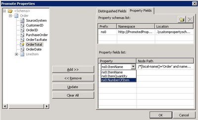
Once the property schema is picked, you can start promoting message elements as promoted properties. To do so, click a message element and click on the add button, the Node Path column will display the XPath to the message element you are promoting and the Property column let you chose the promoted property that will contain the value of the message element at runtime (see Fig. 1.5).

An interesting side effect is that Manual Promotion let you have promoted properties with different names that the original message element name. This might be useful when a same property schema is used to hold promoted properties from different message types or when a message has different element with the same name.

Using Manual Promotion, it is also possible to promote message elements to promoted properties in the system property schemas shipped with BizTalk. To do so, just browse in the References sub-tree when picking the property schema (see Fig. 1.4).
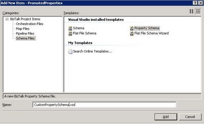
BizTalk - Create a property schemaFig. 1.2 Manually create a custom property schema
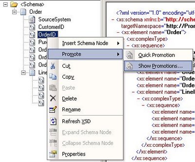
BizTalk - Promoted Properties, manual promotionFig. 1.3 Manual Promotion

BizTalk - Promoted Properties, selecting a Property SchemaFig. 1.4 Selecting a Property Schema

BizTalk - Promoted Properties, selecting the promoted propertyFig. 1.5 Selecting the message element to promote and the promoted property that will contain the message element’s value.

1.3 How to promote properties through the BizTalk API?

As I already said in a previous post, BizTalk Messaging Architecture, context properties are stored in a property bag, an object which implements the IBaseMessageContext interface. This interface contains 2 methods which take the same parameters (a property name, an XML namespace, and value for the property).

a. The Write() method is used to write the property value into the message context without actually promoting it. It can be used to write distinguished fields or to write transient values. Calling the Write() method is NOT promoting a property, it is writing a property.

b. The Promote() method is used to write the property value into the message context but also flags the property as promoted so that it is available for routing. This is the method that needs to be called to promote a property.

To promote a property through the API, element name and namespace passed as parameter of the Promote() method must be those of the property defined in the property schema. They are most easily accessed by referencing the property schema assembly and using the properties on the class created for the property.

Example of promoting a property through an API call (copied from the BizTalk 2006 MSDN documentation: Processing the Message):

//create an instance of the property to be promoted
SOAP.MethodName methodName = new SOAP.MethodName();

//call the promote method on the context using the property class for name and namespace
pInMsg.Context.Promote(methodName.Name.Name, methodName.Name.Namespace,
“theSOAPMethodName”);

As I mentioned before, it is possible to promote properties to the BizTalk system property schema using Manual Promotion in Visual Studio’s Schema Editor for BizTalk. It is possible to achieve the same programmatically and as for other promotion, the name and namespace passed in parameter of the Promote() method is the one of the promoted property in the property schema, the system property schema namespace in this case.

//BizTalk system properties namespace
private const string BTSSystemPropertiesNamespace = “http://schemas.microsoft.com/BizTalk/2003/system-properties”;

//Promote the MessageType property
string messageType = “http://” + “schemas.abc.com/BizTalk/” + “#” + “Request”;
message.Context.Promote(“MessageType”, BTSSystemPropertiesNamespace, messageType);

2. Distinguished fields

2.1. What are distinguished fields?

Distinguished fields are message elements that are written into the message context. They differ with promoted properties in 2 main aspects:

  • They are not flagged as promoted in the message context and so are not available for routing by the Messaging Engine (adapters, pipeline…). Their typical use is instead for the orchestration engine.
  • They are not defined using a property schema.

Distinguished Fields are WRITTEN in the message context by the pipeline when a message is received on a port. It is usually the job of the disassembler pipeline component such as the XML and Flat File disassembler but any custom pipeline component can also do it.

Distinguished fields are useful when a message element value needs to be accessed from an orchestration. Instead of having the orchestration engine search through the message to evaluate an XPath expression (which can be resource-intensive on a large message), a distinguished field can be used. Distinguished fields are populated in the message context when the message is first loaded. Consequently, each time the distinguished field needs to be accessed, the orchestration engine will directly read it from the message context (a property bag object) instead of searching for the original value in the message with XPath. Needless to say that retrieving a single value from a property bag object is much faster than evaluating an XPath expression.

Distinguished fields also offer IntelliSense in the orchestration expression editor which enhances code readability.

2.1 How to create a distinguished field?

The main source of confusion between distinguished fields and promoted properties is that they are both created in Visual Studio’s Schema Editor through the Promote -> Show Promotions contextual menu option of a message schema’s element. Once the dialog box is open, make sure that you are on the Distinguished Field tab, select the message elements and click the Add>> and <<Remove buttons to add and remove distinguished fields (see Fig 2.1).
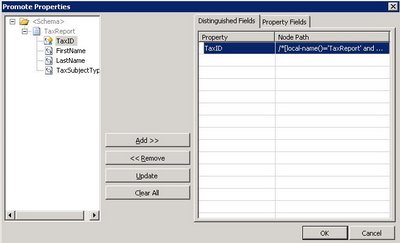
BizTalk - Creating Distinguished FieldsFig 2.1 Creating a Distinguished Field.

2.2 How to create a distinguished field through the BizTalk API.

Distinguished fields are written into the context using the Write() method on the IBaseMessageContext object. To be recognized as a distinguished field, the namespace of the property must be “http://schemas.microsoft.com/BizTalk/2003/btsDistinguishedFields”. Pipeline components delivered with BizTalk do not use those context properties. It is nevertheless possible to read/write distinguished field in the code of custom pipelines, as for any other context properties.

Example of writing a distinguished field through an API call (taken from the BizTalk 2006 MSDN documentation: Processing the Message).
//write a distinguished field to the context
pInMsg.Context.Write(“theDistinguishedProperty”,
“http://schemas.microsoft.com/BizTalk/2003/btsDistinguishedFields”,
“theDistinguishedValue”);

Would you use another namespace, it will result in writing a plain transient value in the property bag and won’t be recognized as a distinguished field by the orchestration engine.

//Write a transient value to the message context
message.Context.Write(“MyVariable”, “SomeNameSpace”, SomeData);

3. Considerations, similarities and differences between promoted properties and distinguished fields.

3.1 Performance considerations:

  • Promoted properties are limited to 255 characters for routing performance reasons. Properties that are simply written in the context (such as distinguished fields) are not limited in size but large properties decrease performance.
  • All Context properties (both Promoted and Distinguished Fields) are stored separately from the message in the Message Box Database. Consequently consuming more space in the BizTalk databases but more importantly incurs more load when persisting/reloading the message in/from the DB. Note that if tracking is turned on, Promoted Properties are also stored in the Tracking database.
  • Distinguished Fields cost less than Promoted Properties in terms of performance. Both Promoted and Distinguished Fields require the same overhead of writing their values to the context Field bag in the Message Box database, but Promoted Fields have the additional overhead of being written in BOTH to the Message Box context tables AND the subscription tables. Distinguished fields are not stored in the subscription table as they do not participate in routing.
    Promoted Fields have an impact every time a message is written in the Message Box because each Promoted Property that exists must be evaluated in a massive T-SQL union statement that builds the list of matching activation subscriptions. In short, the more Promoted Fields you have the more costly the subscription process is.

3.2 Other considerations

  • Both promoted properties and distinguished fields are populated when a Pipeline Disassembler Component parses a message and either Promotes or Writes the value to the message’s context.
  • Empty pipelines such as the Pass-through pipeline do not promote or write anything in the message context as it lacks a disassembler component.
  • Writing a value into the context with the same name and namespace that were used previously to promote a property causes that property to no longer be promoted. The write essentially overwrites the promotion.
  • Writing a property in the context having a null value deletes the context property altogether because null-valued properties are not permitted.

3.3 Distinguished and Property Fields Difference Summary.

  • Promoted Fields should be used for routing, correlation and/or tracking.
  • Distinguished fields should be used when a particular message element is commonly manipulated in one or more orchestration.

Here is a table outlining the main differences between both types of fields:

Promoted Fields (aka Promoted Properties) Distinguished Fields
Used for routing (subscription mechanism)
IsPromoted = true
Do not participate in routing
IsPromoted = false
Used for tracking Not used for tracking
Restricted to 255 characters No size limitation
Available for use in orchestrations Available for use in orchestrations
Require property schema Do not require property schema
Used by standard pipeline components Accessible only by custom pipeline component which would explicitly access them

4. References.

MSDN – The BizTalk Server Message
MSDN – Processing the Message
MSDN – About BizTalk Message Context Properties
Neudesic’s blog – Distinguished fields myths
Windows Process, .Net Application Domain and 2 GB limit on 32-bit Windows

A few weeks ago I heard some comments from a colleague about how .Net applications run and that “all .Net applications run in the same runtime (CLR) so that if you start 10 separate .Net applications, they would share together a single 2 GB limit on Windows 32-bit”. This of course not true and it gave me the idea to blog about the 2GB limit on 32-bit systems, Windows Process, .Net applications and the concept of .Net Application Domain.

2 GB limitation on Windows 32-bit.

32-bit Operating Systems are capped by the number of unique pointers that can exist at a time. On 32-bit processors, only 2^32 distinct addresses can exist. Would all these addresses be used, that would represent 4 GB of memory. On a Windows Operating System the memory address system is not a 1-to-1 relationship to the physical memory of your hardware otherwise you would be stuck with a maximum of 4 GB of addressable memory for the whole machine. This would include all the I/O address space, kernel memory and so leave much less actual memory for programmers to use.

This is why when we talk about memory, it is important to realize the distinction between the physical memory (RAM on the motherboard) and the Virtual Memory accessible through the Virtual Address Space. Note that actually, Virtual Memory is not the same as Virtual Address Space and that there are ways to use Virtual Memory without using the Virtual Address Space. I will nevertheless not go into these details; the important thing to remember is that Windows has a complex memory management system that enables the O.S. to use much more than 4 GB as a whole. The inner workings are not for the faint-hearted and are actually not of interest for most .Net programmers living in the managed world.

Check this blog post for a primer on memory management on Windows Operating System.

When Windows 32 starts a program, a 32 bit process using 32 bit size pointers is created and so the process has a maximum of 4 GB of addressable memory.
Windows will assign to the process a Virtual Address Space of 4 GB (2^32) split in two; 2 GB of user mode virtual address space and 2 GB of kernel mode virtual address space. The user mode virtual address space is the “memory” (read the virtual address space to be correct) available for your program to use.
This 2 GB user mode virtual address space limit is what is commonly called the 2 GB memory limit on Windows 32-bit.

/3 GB switch on 32-bit Windows

The /3GB switch changes the way the 4GB virtual address space is split up. With the /3GB switch, the split is 3GB of user mode virtual address space and 1GB of kernel mode virtual address space. It is nevertheless not recommended to use this option as it can bring unexpected bug from drivers and other kernel-mode processes which might expect to have 2 GB of kernel virtual address space available (not that a driver would ever need 2 GB, just that an older driver might expect to have addresses from 0x80000000 to 0xFFFFFFFF available).
See here and here for other problems that can arise when using the /3GB switch.

AWE

AWE does not give more virtual address space to a process. AWE stands for Address Windowing Extension and is a Microsoft API (Application Programming Interface) that allows a 32-bit software application to access more physical memory that it has virtual address space.
AWE enables programs to reserve physical memory as non-paged memory and then to dynamically map portions of the non-paged memory to the program’s working set of memory. This process enables memory-intensive programs, such as large database systems, to reserve large amounts of physical memory for data without having to be paged in and out of a paging file for usage.
To be clear, AWE can only be available on programs that actually use the AWE API, it is not an OS switch that can be turned on/off on any program.

Windows 64-bit

On windows 64-bit there is not 2 GB limit, the user mode virtual address space limit being 8TB. See here for reference.

Windows Process and Runtime Host

A Windows process is an instance of a program that is executing over the Windows layer. A process contains the executable code and data inside the memory reserved for it by the Operating System. There will be at least one thread executing instructions within the process but more in most cases.

Any program running on Windows is actually working within a process. If you open 2 instances of notepad, you can see that 2 processes running notepad.exe are visible under the Processes tab of the Windows Task Manager.

The concept of a Process exists for two main reasons:

  • To enable multitasking (time sharing), the different processes a CPU is running will have their states changing between running and waiting very quickly and so give the illusion to the end-user that all processes are running in the same time. This brings multitasking as well as scalability.
  • To provide boundaries between running programs so that a process cannot peak into another one and that erroneous code inside a process cannot corrupt areas outside of that process (so that a process cannot crash another one). This is brings security and stability.

The isolation between processes is achieved by making sure that any given unique virtual address space runs exactly into one process and not any other.

Runtime Host

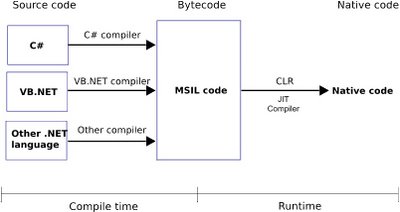
.Net applications are compiled in CIL (Common Intermediate Language, formally called MSIL – Microsoft Intermediate Language), and then are JITed (Just-In-Time compiled) by the CLR (Common Language Runtime) into instructions directly understandable by the CPU (native code).
Here is an illustration of this 2 step compilation process:


This means that .Net applications are not Win32 applications and so cannot be executed directly by the Operating System. As any application running on Windows has to run through a Windows Process, a Windows Process called a Runtime Host will actually execute (host) the .Net Application. The Runtime Host first loads the CLR dll (a native Windows library – unmanaged code) which in turn loads the .Net application (managed code), JIT compiles it and runs it. The process thus effectively transitions the control of running the application from itself to the CLR.

There are 2 types of Runtime Host shipped with the .Net Framework, ASP.NET and Shell. Shell runs all Windows-type applications (Windows Form, Windows Service or Console App).

We can see that this concept actually adds a new layer between the .Net application and the Operating System. This layer, implemented by the CLR, is generically called a Virtual Machine and has OS-like features. It is an abstraction layer between the .Net application and the Operating System. As with Java, this permits any .Net Application to run on any Operating System as long as there is a CLR implemented for that OS.

2 GB limit for .Net applications

As the Runtime Host is a Windows Process, the .Net applications run by a Runtime Host is limited to the 2GB barrier on 32-bit Windows OS. Nevertheless, every Runtime Host has a separate 2 GB virtual address space limit. So would you launch 2 instances of a .Net application, each being a separate process in Task Manager, they would each have 2 GB limit.

.Net Application Domain

An Application Domain is the CLR equivalent of an Operating System’s process. As the Windows OS brings logical and physical isolation between Windows applications through the use of Processes, a single Runtime Host Windows Process can run several isolated .Net applications through the use of Application Domains. As explained before, Windows isolate processes by assigning different virtual memory address space to each process. In the .Net world, the memory is actively managed by the CLR and so the CLR can make sure that memory addresses are not shared between application domains, effectively isolating different Application Domains running in the same Runtime Host.

When a Runtime Host starts a .Net application, the CLR will create a default Application Domain to run the .Net application. As multiple Processes can run on a single OS, multiple Application Domains can run within the same Runtime Host.

An Application Domain is cheaper to create than a Windows Process and has relatively less overhead to maintain. It is thus more efficient to isolate .Net Application through Application Domains rather than Windows Processes. Application Domains are sometimes referenced as lightweight processes but strictly speaking, they are NOT processes.

To summarize, here is a list of advantages of having Application Domains within a Runtime Host Process (which are for most of them similar to the advantages of having Processes within an Operating System):

  • An Application Domain is a more lightweight mean to provide isolation between .Net applications than Processes.
  • A .Net application in an Application Domain can be stopped without affecting the state of another application running in a separate Application Domain.
  • A crash in an Application Domain will not affect other Application Domains neither the Runtime Host Process hosting the Application Domains.
  • Configuration information is part of an Application Domain scope, not the process’ scope.
  • Each Application Domain can have different security access levels assigned to them, all within the same Runtime Host Process.
  • Code in one .Net Application Domain cannot directly access memory in another Application Domain. If two .Net applications need to communicate across Application Domains, they need to use .Net Remoting to do so. In .Net 1.x, this kind of inter-process communication was expensive because the TCP/IP stack needed to be involved. In .Net 2.0, .Net Remoting supports named pipe remoting which is much more efficient. WCF in .Net 3.x has this feature as well.